THE COMPACTOR
Compactor types
Although the general layouts of roll compactors look alike, there
are some features that differ from compactor to compactor. These lead to a type classification:
· Roll assembly: fixed / movable rolls
· Sealing: Side plate assembly / rim roll assembly
· Auger design: constant diameter and slope / decreasing diameter
or varying slope
· Auger assembly: one / two augers
· Roll layout: vertical, horizontal, skewed
Roll layout
The relative position of the rolls towards each other is mainly a matter
of design and therefore it only plays minor role (the 30° skewed position
of Gerteis compactors for example results from the wish to easily harvest
long ribbons during the running process while the integrated milling equipment
is running).
Figure: Different roll assemblies: horizontal (left), skewed (middle)
and vertical (right)
Only the vertical assmbly might give some reasons for concern:
· If the draw in angle is fairly small, powder that is fed to
the nip area might remain at the gliding zone since gravity force is not
overcome by friction to the roll surcace (see next fig., left). Thus
particles that stay at this position might show an increase in their temperature
and are susceptible for increased degradation.
· The situation concerning the direction of force by friction
and force of gravity is completely different for the two rolls. Therefore
the nip angles at upper and lower roll differ.
Figure: Powder might stay in place if nip angle is quite small giving
reason for concern regarding thermal degradation (left) and major differences
in nip angles should be taken into account when using vertically assembled
rolls.
Fixed vs. movable rolls
The rolls of a compactor might be assembled next to each other in a fixed
position. This results in a fixed gap size, which is the result of the
distance between the roll centers and the roll diameter. Therefore, this
gap size can not be changed during the process. The force applied during
the compaction process results from the amount of fed powder per time and
the powder’s compression properties but cannot be controlled properly.
Compactors with movable rolls are equipped with one roll, that is assembled
in a fixed position in respect to the housing (master roll) and a movable
roll (slave roll). The slave roll either slides on tracks or pivots on
a lever. The compaction force is applied by hydraulical units and might
be adjusted, changed or controlled during the process independent from
other process settings.


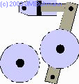
Figure: Roll assembly: fixed rolls (left), and movable rolls (sliding rolls,
middle; pivoting rolls, right)
Side sealing
In order to prevent the powder from finding its way around instead of through
the compaction area, the rolls have to be sealed at their sides. This might
be achieved either by a side plate assembly or by rimmed rolls.
A typical side plate assembly consists of two strong side plates (one
for each side of the gap) that are slightly pressed against the rolls.
In order to prevent metal-metal friction and wear, a PTFE-platelet is positioned
in between.
Since the degree of densification might be quite high in the compaction
area, the side plates might be bent to the sides by the high transversal
forces. This leads to insufficient sealing which in return allows powder
to escape from compaction. Therefore the ribbons edges might be weak and/or
crumbling.
The other sealing system is the so called rim roll assembly where one
roll is equipped with two rims (one at each side of the roll) while the
other roll runs within this cavity. Since the rims are mounted to the roll,
they can stand high transversal pressure without losing their sealing capability.
Therefore ribbons produced on rim roll systems exhibit strong, non fragile
edges.
Auger design
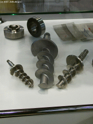
The auger screws might be of cylindrical or conical shape and also the
slope might be constant or changing and any combination thereof.
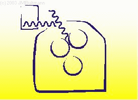
Figure: Different auger designs
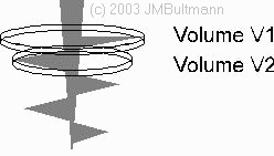
By varying the slope and/or a conical outline, a predensification of
the powder might be intended (see figure). One has to keep in mind, that
by densifying powder that shows local changes in powder density, those
changes are not eliminated since the powder is only densified including
those inhomogenities. Other precautions must be taken in order to provide
powder of a homogeneous density to the compaction area.
Figure: Predensification by the tamping auger. If the slope doesn’t
change, the feeding speed reains the same which results in a predensification
from V1 to V2 when the powder is moved forward for half a revolution
Auger assembly
The feeding principle of the powder might rely on gravity transport in
combination with a single feeding auger. Other manufacturers use combinations
of two augers in order to convey the non free flowing powder to the nip
area. The benefit of a two auger layout can be effective air vent and a
more uniform powder transport (expressed as mass per time unit) if proper
control algorithms are used.


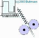
Figure: Different feeding sytems using one or two augers. The auger
design can also differ.
Next to the above mentioned topics, different brands show major differences
in the PLC process controll algorithm and performance.
